MeshCAM
15 Nov 2015I picked up a trial version of MeshCAM, and despite my tendency to edge toward open source software alternatives I must admit MeshCAM is a very good (in comparison to other commercial offerings in this price range) option for CAM code generation. The initial attention grabber for this software was the fact that there's a Mac version, which is nice considering the only reason I have a Windows machine anywhere around my house is to drive my mill.
I'll not repeat a lot of screenshots since all CAM programs will have several features in common (axis home choice, stock size, depth of cut control, etc) and just point out the things unique to MeshCAM and my praises/complaints about those.
Firstly, a word on STL files.
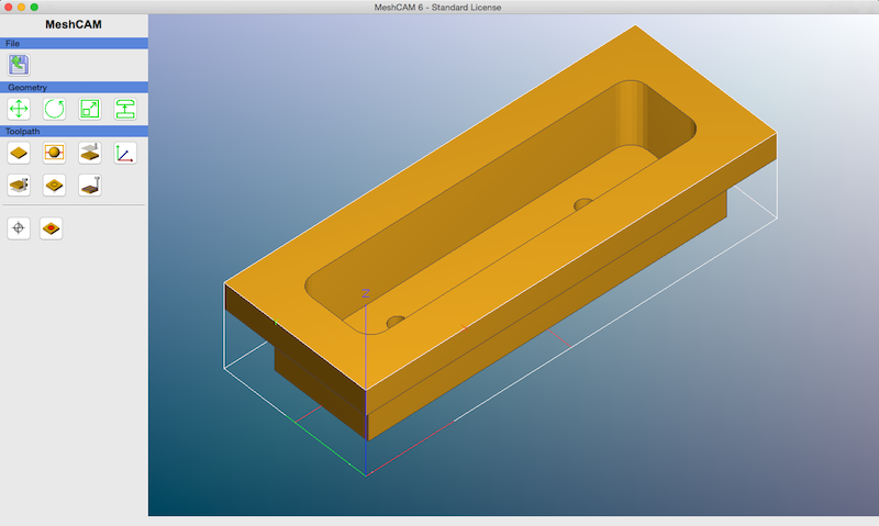
Here's our trusty door pull again and the screen you're greeted with upon opening MeshCAM. There is an option when you open a file asking you whether you would like two-sided, 3d, or 4 axis options. I don't work with 2d files at all, so I won't have anything positive or negative to say about its 2d capabilities. Speaking of 3d, the first glaring bonus for MeshCAM is its preference for (ascii, not binary) STL model files. A lot of CAD/CAM programs support a lot of files but the bulk of them are proprietary and subject to change over time, which can make for a compatibility nightmare. STL support is great for this purpose, since it's royalty-free and widely accepted by other software, particularly amongst the 3d printing crowd.
I'm sure others will argue about how wrong it is to store machine part drawings in a non-line-based format, and admittedly even I still keep DXFs of the parts I draw, but I think the criticism is invalid. All that matters is that your drawing works with your CAM program, and your CAM program can generate working machine code for it. The machine doesn't know or care whether the original drawing was linear or triangle mesh based.
Speaking of the above debate, STL support is actually a pretty good initial test of CAM software for those CAM softwares that support it. If you import an STL and find that the CAM program you're evaluating shows you a garbled mess of triangles and generates a toolpath that will take 3 or 4 hours to cut as it tries to reproduce all of those triangles? Guess what... that CAM program is "stupid" for lack of a better word, the author(s) of it added STL support as a marketing gimmick and didn't test or debug it, and that program can be uninstalled and discarded as a purchase option with confidence at that point.
The other big benefit of STL support for MeshCAM is that you can readily use free/cheap modeling programs without having to pay for a CAD software package. SketchUp will happily export STL models, for example, and can be used for free non-commercially. If you do use SketchUp, you will want to grab a plugin called Solid Inspector to use on your drawings before exporting them from SketchUp. It will tell you whether your drawing is solid or not and can also fix most minor infractions. The catch with SketchUp drawings and STL files is that the STL format is supposed to represent a solid object by defining its faces. If your faces do not intersect completely and properly your object will fail that initial solid test and potentially throw a CAM/3d printing program for a loop.
Anyway, back to MeshCAM's particulars.
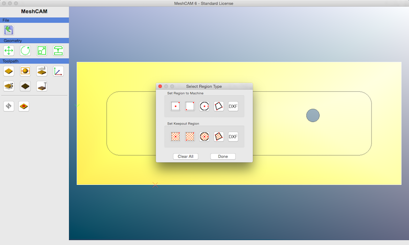
The first button that bears mention is the 6th one under the toothpath menu. Here you can define the region of a part to machine, or the region of a part to exclude from the drawing. This is a pretty simple implementation of that and it works, but this is also the first complaint about lack of features. It would be infinitely more useful to have a measurement scale here with these options, and a means within that measuring scale to go to an absolute point relative to X/Y/Z zero. There's not one, you're just placing these markers by eyeballing them.
That done, on to the toolpath generation options. The following screen is your list of choices when you get to the point of actually spitting out machine code.
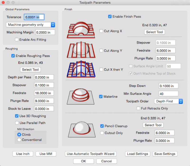
This is a pretty decent set of options, much better than the waste of time that ~~is~~ was Vectric Cut3D. Firstly you can define an entirely 3d toolpath via the 3d roughing, waterline, and pencil finishing options. So our door pull can be cut entirely with 3 dimensional paths without having to worry about stepover issues that could arise from a linear toolpath along a single axis, depending on the tooling used.
Now, there are some (mildly) annoying limitations here...
- "Stock to leave" on the roughing options is absolute, and affects all axes.
- Waterline finishing shares the tool choice with the X/Y/criss-cross finishing options.
The stock to leave shortcoming is the most critical, but it can be fixed with a little trickery. The problem with a setting that affects all axes is presented with our door pull. Consider the following tool path, generated with MeshCAM, to rough and finish the inside of the door pull...
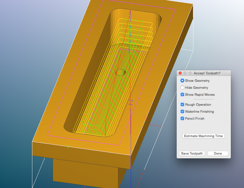
The green lines are the roughing toolpath, the yellow lines the waterline, and the purple line at the bottom of the hole the final finishing pass at full depth. This is the most efficient way to cut this part and using a tool with an appropriate diameter will leave you with the proper corner radius in each corner in the shortest period of time. Optimally, I want to rough out the bulk of the plunge cutting at the ragged edge of the speed/feed limits of my machine and tool, then I want to go back and finish the last few thousandths of the cut with a slower feed rate to leave a nice smooth finish. The problem is, defining a "stock to leave" in MeshCAM of say, 10 thousandths, will affect not just the walls of the inside of the door pull, which I want to get a finishing pass, but also the depth which I don't need to get a finishing pass. So that 10 thousandths depth restriction will also leave me with 10 thousandths of extra material at the bottom of the door pull. That won't work. It would be a lot more useful if MeshCAM had stock to leave settings for both X/Y and Z individually, that way I could let it rough the full depth by defining a stock to leave on Z of zero, while leaving my 10 thousandths on X/Y. Thankfully, MeshCAM does have an easy way to circumvent this. When you go to define your tools in MeshCAM you'll find if you try to duplicate them by number that the tool numbers are not unique. So in my case my primary roughing tool is #3, a 0.375" diameter flat end mill with a 1.125" flute length. While I can't define extra stock to leave in the X/Y axes while leaving Z roughing at a different depth in MeshCAM, I can define another #3 tool with the same flute depth and the same tool number, but a different diameter of say... 0.390" instead of 0.375". That way when the code is generated it will accomplish what I'm after, and leave 7.5 thousandths on the walls but not the bottom of the door pull, just in a roundabout way.
The waterline finishing option being limited to the same tool as the X/Y finishing options is a very minor oversight, but worth mentioning I suppose. If I were say...dry cutting a very soft aluminum which tended to leave a folded edge, and I wanted to cleanup those edges with a flat tool but waterline finish a bevel with a ball tool, I wouldn't be able to do so easily (I'd have to generate toolpaths twice and manually merge them). There are few cases I can think of where this might be useful for what I'm doing so I'm not gonna harp on it much.
All in all, MeshCAM is a very capable CAM program for the price. It would be nice to have a few more features, but I can generate toolpaths to make my semi-complicated door pull in about 20-30 minutes on my very humble machine, so it's working for me. If you need a CAM program particularly on a Mac, it's worth trying out.